
I got bitten by a little APRS bug this week, right after I finished assembling my K3 while waiting for the power supply and coax to arrive. I wanted an antenna we could mount on the top of Lauren’s minivan for any roadtrips we might take. But because it is not MY car, there are quite a few more restrictions. Like: no holes in the car; no physical changes to the car; not ugly (beauty is in the eye of the beholder?); why do we need an antenna again? I also placed the restrictions on it that it must be cheap (or free), easy to build, and work at least as well as my SMA-24, which is my most-commonly used HT antenna.
I started off with a Google search of homebrew 2m antennas to find that pretty much people make j-poles or 1/4-wave vertical antennas; neither of which look good on top of a minivan. I searched more, for low-profile antennas. I suppose I could have come up with a coil-loaded whip of sorts, but I wanted something cooler. I finally found a great write-up on how to build a 2m DDRR antenna. I had never heard of a DDRR antenna before, but being fairly new to the hobby, there are a lot of things I have never heard of. DDRR means Directional Discontinuity Ring Radiator or Direct Driven Ring Radiator, depending on where you look, was originally invented by J.M. Boyer for use on ships. It consists of a 1/4-wavelength element, grounded at one end and wound into a single coil, a short distance above ground. Because I found W5GVE’s article before the W6WYQ’s 1971 QST “A 40-Meter DDRR Antenna” article, I followed the W5GVE instructions, which differ slightly. The biggest difference being the height of the antenna and the feed point. I may have to try again following W6WYQ’s plans.
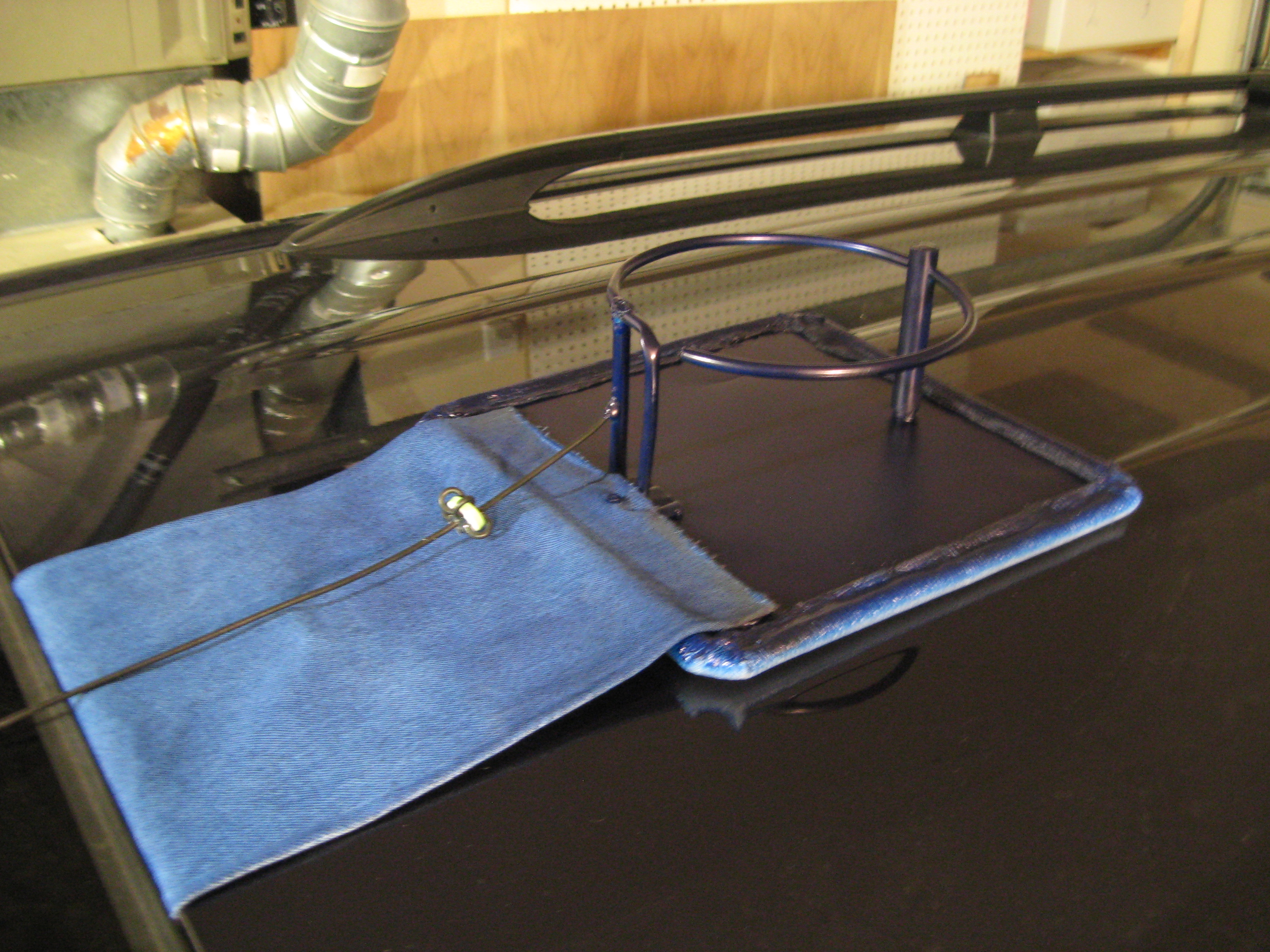
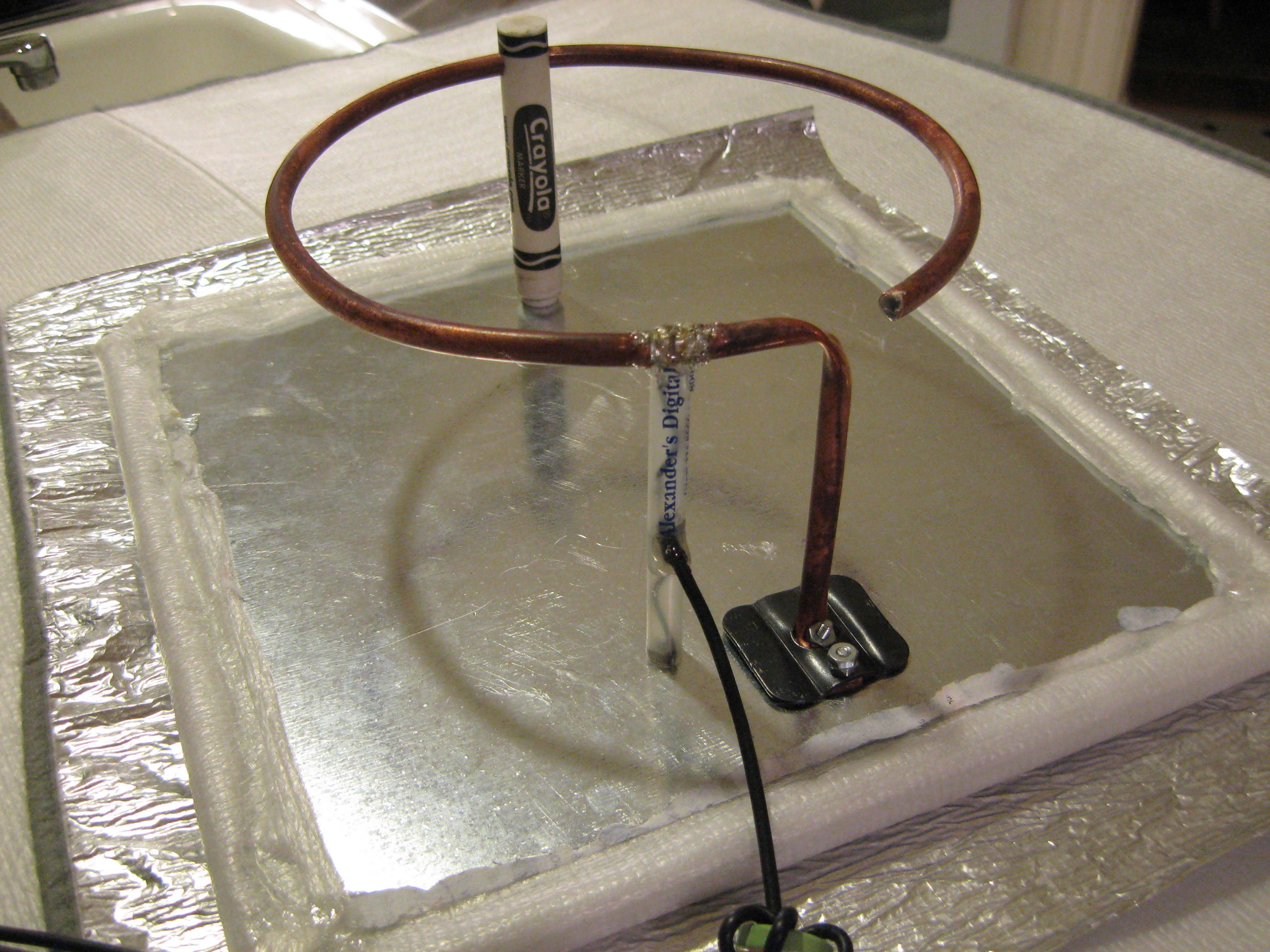
I started with a piece of 1/4″ copper flex tubing and bent it around a #10 tin-can, which is just about 6 inches in diameter. I made a 3 inch tail with a short flange for the ground contact. For the ground plane, I found a piece of ducting sheet metal lying around. With a small piece of angle-iron and some #4 metal screws, nuts and washers, I made a secure mount for the radiator, which was now starting to look like a heavenly halo (so say the kids). Using a small strip of tin soldered to the feed wire and crimped around the tubing, I was able to adjust the feed point for optimal radiation. Once in place, I slipped the feed wires into an old empty pen for mechanical reinforcement. I marked the spot an soldered the feed point in place. I used another screw and nut to connect the shield of the coax in place below the feed point, mounting the pen over the nut. For more stability, I used an old Crayola marker tube on the side of the ring opposite the ground. I added padding to the bottom and sides so it wouldn’t scratch its precious bearer, painted it for camouflage, and viola! it was finished. Oh, I almost forgot to point out that I also added means to mount the antenna: a strip of fabric connected to the front and a rope across the back to keep it down. I think it will serve usme well.
For testing throughout the development process, I used my HT at 0.5W and 5W to transmit APRS packets and to use voice. APRS is nice because if it hits a digipeater I get my packet transmitted back to me. Voice is nice because I can get a bona-fide signal report. I am not sure about the actual electrical specifications of this antenna because I do not have an antenna analyzer, a SWR meter, dip meter or anything of that sort, but it works and I think that is a good indication of how well it works.
I suppose the real test is if Lauren will let me use it on her minivan. See my antennas album for more pictures.